
Average opening effort
The average of accepted opening estimates. The range verdict compares this with the configured easy/hard bounds.
Operating manual
Set up your SCUBA Regulator Tester, confirm the pressure reference, and record SCUBA second-stage opening-effort checks. Keep the test conditions with every maintenance and servicing result.
01 · Local connection
Power the tester from USB or its fitted battery. The display and buttons work without a phone; use the local web interface for activation, detailed setup, charts and exports. You do not need to connect the tester to your home network.
Scuba-Regulator-CPT-XXXXXX.scuba-test.| On the display | Meaning |
|---|---|
AP0, AP1… | Hotspot active; the number is connected clients. |
LAN with arcs | Joined to the saved network; arcs show last known signal strength. |
| Blinking dots | Trying to connect. |
| Amber icon | Waiting to retry, or retry deferred until the test ends. |
Open MENU → Wi-Fi for network/IP details, setup instructions, reconnect, hotspot-only mode or confirmed forget. Hotspot-only pauses the saved network without deleting it and survives restart. Forget keeps the hotspot available. Network changes are locked while a measurement is running.
A LAN connection shows that the board joined Wi-Fi; it does not assert internet access. Use the hotspot address above if local hostname discovery is unavailable.
02 · Activate your board
If needed, complete the USB firmware installation first. Then follow the hotspot connection steps above to open the device interface.
Power the board and open its local browser interface. Copy the 12-character Device ID from About. Wi-Fi setup, Device ID and activation remain accessible before purchase.
Copy the Device ID, then switch back to your normal internet Wi-Fi or use another internet-connected device. Check licence availability and purchase the €25 lifetime licence for that board. Save the full activation key from your confirmed order. Measurement, tests and records require activation.
Rejoin the tester hotspot and reopen http://192.168.4.1. Under About → Activate device, paste the full matching key and select Activate device. The board checks the key locally, without internet. Confirm that it reports an active licence. Measurement also works offline.
Your FiddlerCrab account retains board registration and completed installation history. Keep purchase receipts and activation keys private. Open registered boards →
03 · Two-button control
| Action | Result |
|---|---|
| MENU · short | Open the quick menu, then advance to the next item. |
| MENU · hold | Close the menu and return to Live. |
| SELECT · short | Choose the highlighted menu item; from the activated Live/result screen, start a ready test. |
| SELECT · hold | Cancel the active test and zero the sensor. |
External MENU uses GPIO1; external SELECT uses GPIO2. The on-board GPIO0 / GPIO14 buttons provide the same controls. The quick menu also includes zero, target breaths, chart window and brightness.
04 · First breath set
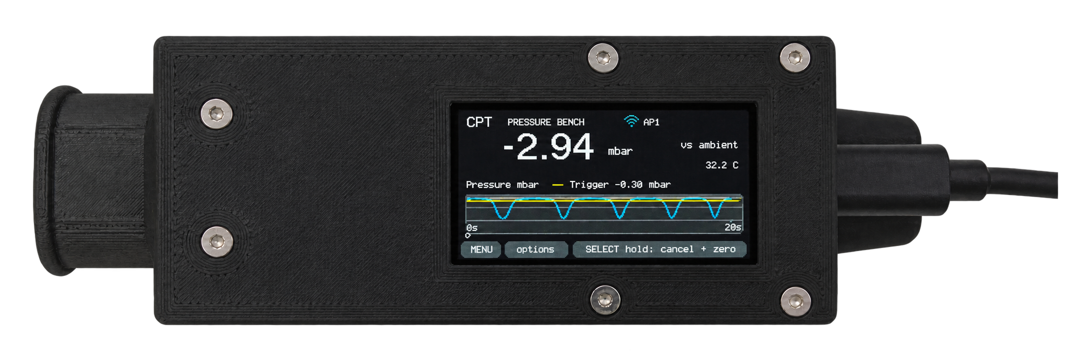
With assembly, activation and the instrument checks complete, fit the tester between the second stage and its mouthpiece. Follow the regulator manufacturer’s bench setup and service procedure; keep the tester’s ambient reference open. The airflow diagram shows which pressure path is measured.
Power the instrument with both pressure ports at equal pressure. Startup performs a non-blocking zero. Keep the pressure steady while the readiness checks finish.
Confirm its seal, sensor orientation and pressure response against the reference arrangement. Inhalation should read negative. If the sign is reversed, verify the connections and use Reverse sensor ports when appropriate.
In Test setup, enter the serial number, model/profile, technician, work order and relevant bench conditions. These fields belong to this test; they are snapshotted with the result.
Set the required range, repeatability limit and breath count. Ten accepted breaths is the default; 2–20 can be selected. The correct model-specific procedure determines the appropriate targets and control positions.
The sensor, tare, stable-zero window and record storage must all be ready before a physical test starts. Resolve the displayed reason if the start control remains unavailable.
Confirm the live pressure is near 0.00 mbar at rest and becomes negative during inhalation. Start the breath set with SELECT or the web interface, then take slow, repeatable breaths. Keep the technique and bench conditions consistent across breaths. Watch the accepted-breath count reach your chosen target. Review the completed result and waveform, then find the saved set in Records. Accept service results only when the physical reference checks also support them.
05 · Read the result
The average of accepted opening estimates. The range verdict compares this with the configured easy/hard bounds.
The standard deviation across the accepted breath set. Its verdict compares variation with your configured limit.
PASS requires both the average to lie in range and the breath-to-breath variation to remain within the limit.
Blue: measured pressure. Orange: the breath-detection trigger. In the web chart, a shaded band marks the configured target range. The trigger is a detector setting, not the desired service opening value.
The detailed report preserves each breath’s peak, duration, ramp-rate and opening marker. Readouts rounded to zero show 0.00; real rounded positive/negative values keep their sign.
06 · Keep the evidence
Use Records to review the completed breath set, compare drift, open the detailed printable report, export CSV or download raw NDJSON backup. Every result retains its own service metadata and bench conditions.
The Acceptance simulator exercises the detector, chart, verdict and record path with labelled PASS/range-fail/repeatability-fail examples. Simulator records are permanently tagged and excluded from normal record/drift views by default. They are software examples, not physical service measurements.
Export the raw record backup. Choose Update only to preserve settings, calibration, history and the installed licence. A new installation or erase is for a blank/recovery board and removes stored data; read the installer’s selected-mode notice before proceeding.
07 · Reference and calibration
Zero at equal pressure to remove the current offset. For span adjustment, use a stable signed reference pressure and the web calibration tool; confirm the corrected response at suitable reference points.
Record the reference, date and due date in Settings. Those fields document your checks; they do not independently certify calibration. Keep clean, non-condensing gas and liquids away from the sensor connections.
The pressure-only algorithm estimates opening as a local minimum followed by a sustained rebound. It cannot observe the intermediate-pressure gauge drop. This instrument does not measure work of breathing or establish compliance with breathing-apparatus standards; use the correct service procedure, calibrated bench and model-specific checks.
08 · Troubleshooting
Remove power, then recheck VDD to 3.3 V, GND, SCL to GPIO17 and SDA to GPIO18 against the numbered sensor bottom view. Confirm an SDP810-500Pa at address 0x25. The diagram’s pin order is not a top view.
Open wiring →Check that the duct and ambient references reach the intended sensor ports. Confirm the selected pressure direction; use Reverse sensor ports when needed. Re-zero at equal pressure and verify against the reference again.
Keep both pressure sides steady at equal pressure, then wait for the stability window. Check the pressure path and sensor connections for leakage, movement or contamination. The display names the readiness condition that remains incomplete.
On the standard four-leg tactile switches shown, either pair of diagonally opposite legs is correct. Connect one to the button GPIO and the other to GND. If needed, check with a continuity meter: the pair must be open at rest and connect only while pressed. Ensure neither GPIO1 nor GPIO2 is shorted permanently to GND.
Join the displayed device hotspot and open http://192.168.4.1 directly. Check AP client count on the display. MENU → Wi-Fi → Network details shows the active IPs; hotspot-only mode can pause workshop Wi-Fi without deleting it.
Compare the board’s 12-character Device ID with the order. The key is bound to that board and the CPT product. Use the full key in the local About → Activate device panel. Keep the key private when asking support for help.
Compare the finished instrument against the pressure reference, then check the body, mating seals and sample connection. Keep the ambient reference unobstructed. A pressure waveform alone cannot replace the prescribed dual-gauge service method.
The full-size diagrams remain available in the build guide.