
Build guide
Build your SCUBA Regulator Tester.
Follow this guide from your shopping list to an assembled SCUBA Regulator Tester. Start with the parts and matching model files, then wire and check the electronics on the bench before final assembly. Keep the measured pressure path separate from the electronics bay.
01 · Parts list
Only the parts this tester needs.
Check licence availability before ordering parts. Measurements require an activated device licence.
The ST7789 display, Wi-Fi and USB interface are built into the T-Display-S3. The pressure sensor connects directly to the board over I²C.
| Qty | Part | What to check |
|---|---|---|
| 1 | LilyGO T-Display-S3 | Basic, non-touch board with ST7789 170 × 320 display and 16 MB flash. Official board reference ↗ |
| 1 | Sensirion SDP810-500Pa | Tube-connection digital differential-pressure sensor, address 0x25. Manufacturer datasheet ↗ |
| 2 | Normally-open tactile switches | Current CAD uses a 6 × 6 × 3.4 mm body envelope. Compare the actual stem height and terminals with the clips before ordering. |
| 1 set | Printed body, lid and two clips | Use the matching v0.14 package: body, lid and two button clips. Download the model and print profile. Check your actual print for fit and leaks before use. |
| 6 | M2.5 × 10 countersunk screws | Use the specified length and dry-fit. Longer screws can compromise the blind screw-pilot floors and pressure passage. |
| — | Direct-to-plastic fastening | No inserts. The body has 2.1 mm blind pilots and the lid has 2.8 mm clearance bores. Keep the blind floors intact. |
| 1 optional | EEMB LP852040 / 852040 LiPo battery ↗ | 3.7 V, 620 mAh; finished pack up to 42 × 20.5 × 8.8 mm. The v0.14 housing provides an under-display battery bay; install the cell before the sensor and board. Match the battery plug and polarity to the board’s labelled battery connection. |
| 1 | USB-C data cable | A cable that carries data as well as power, for online flashing and normal USB power. |
| As needed | Short insulated hookup wire | Four sensor connections and two button signals plus their shared ground. Route the actual soldered harness before closing the case. |
| As needed | Pressure connection / sealing supplies | v0.14 seats the sensor barbs directly in bonded body sockets. If a tubing connection is used, match tubing to the actual barbs and keep the two paths separate; no tubing dimensions are assumed here. |
You will also need a 3D printer or a printing service, soldering tools, a continuity meter and a suitable pressure reference for the finished-instrument check. Adhesive compatibility and cure time depend on the actual printed material and sensor plastic.
02 · Print the housing · v0.14
Compact housing. Optional internal battery.
The body encloses the pressure passage independently of the electronics lid. The battery sits under the display beside the one-sided airway. Reinforced switch supports and positive display stops keep the components in place.
Download v0.14 models · 100% infill X1C profile
Open the included native X1C · 0.4 mm · PLA · Smooth PEI project in Bambu Studio. It uses 0.20 mm layers, 100% infill, five walls and six top/bottom layers; the estimate is about four hours and 82 g. For a different printer, retain the body orientation and review the slice. Keep supports out of the airway.
- Envelope
- 141 × 47.9 × 26.75 mm
- Print profile
- 100% infill · five walls · six top/bottom layers
- Native slice checks
- 6.75 mm longest bridge path; 5.40 mm longest unsupported roof run; no supports inside the airway
- MakerWorld
- Gallery prepared · upload pending
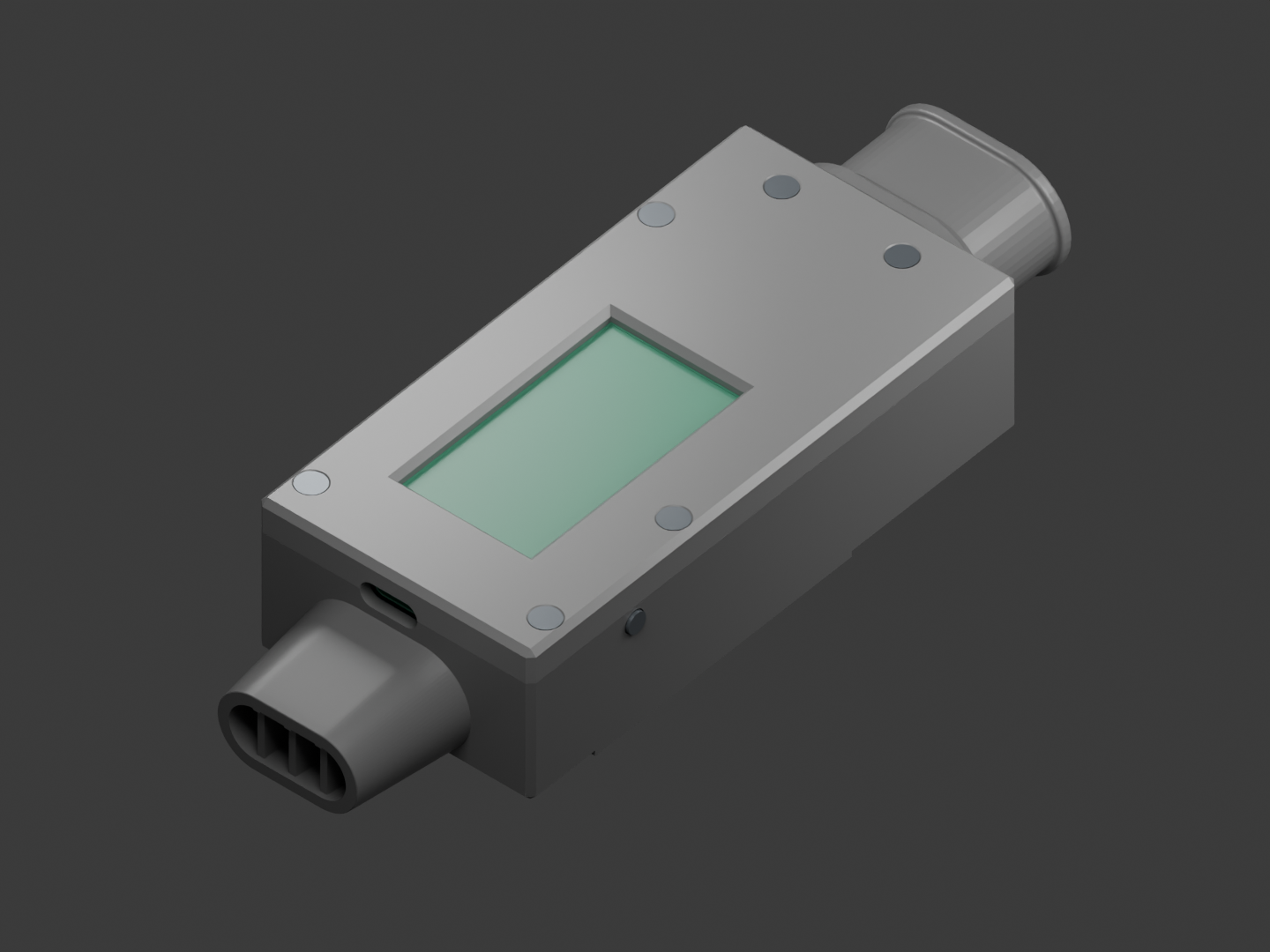
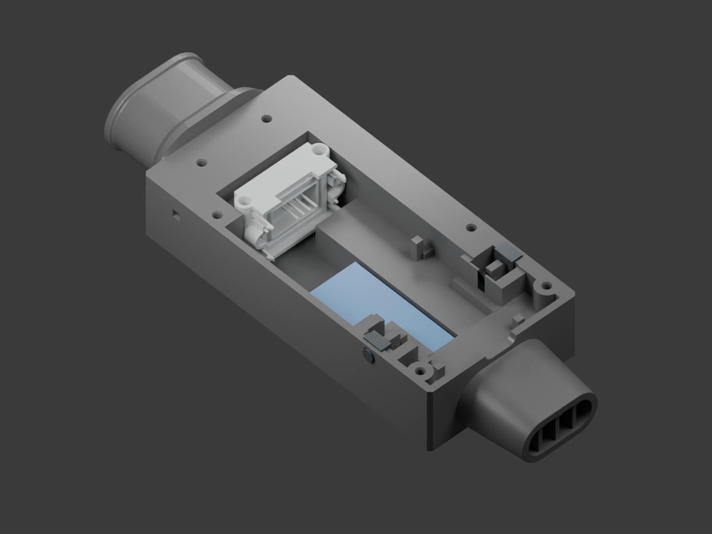
The download includes the matching body, lid, two clips, editable CAD, native X1C PLA project and validation report. Software checks cover the closed airway, component clearances and toolpaths. Check the actual print for fit, leakage and reasonable draw resistance before taking measurements; physical acceptance has not been established by these checks.
For an existing glued v0.11 housing, retain its dedicated retrofit lid. Do not mix the v0.14 lid and body with earlier revisions. v0.9/v0.10 are withdrawn.
03 · Complete wiring
Four sensor wires. Two buttons.
View the T-Display-S3 from its component side with USB at the bottom. MENU uses GPIO1; SELECT uses GPIO2. The on-board GPIO0 / GPIO14 buttons already work and need no added wiring.
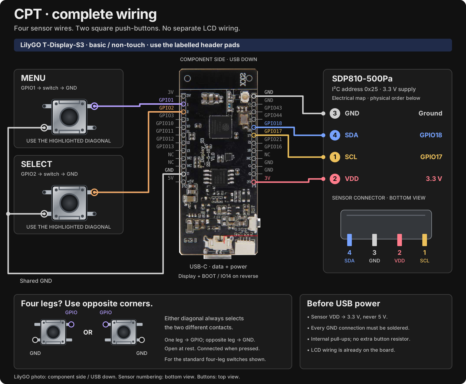
| Sensor pin | Signal | T-Display-S3 header |
|---|---|---|
| 1 | SCL | GPIO17 |
| 2 | VDD | 3.3 V |
| 3 | GND | GND |
| 4 | SDA | GPIO18 |
For the standard four-leg tactile switches shown, use diagonally opposite legs: either diagonal is correct. Connect one selected leg to GPIO1 (MENU) or GPIO2 (SELECT), and the opposite leg to GND. Leave the other two legs unused. The selected pair is open at rest and connects only while pressed. Internal pull-ups are enabled, so no external button resistor is needed.
04 · Check before assembly
Power it on before you fit it in the case.
- With power disconnected, check the sensor wiring and button connections against the diagram. Check for shorts between 3.3 V and GND.
- Keep the board outside the housing and the optional battery unplugged. Use a USB data cable and install firmware in desktop Chrome or Edge. A new board needs Full install.
- Confirm that the display starts, MENU opens the quick menu, and SELECT chooses an item. Open MENU → Wi-Fi to check that the hotspot is available.
- Disconnect USB before fitting the battery, sensor, buttons and board. Continue below with the airflow arrangement and assembly.
The sensor can be wired outside the case for this check. Live pressure readings require activation; the display, buttons, Wi-Fi details and Device ID can be checked beforehand.
05 · Pressure plumbing
The lid is outside the pressure path.
The regulator and mouthpiece join through an enclosed body duct. Connect the sensor’s HIGH (+) side to that duct and its LOW (−) side to a separate ambient reference. During inhalation, duct pressure falls below room pressure, giving a negative reading.
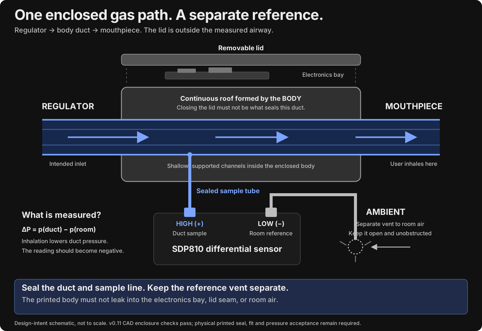
Seal the duct sample connection. Keep the ambient reference open and unobstructed. USB, buttons, screw threads, electronics and the lid seam must remain separate from the measured airway.
06 · Assembly sequence
Fit the real harness before the display.
Use the matching v0.14 body and lid. Complete the bench check before fitting the components. Disconnect USB and leave the optional battery unplugged during soldering and fitting.
Inspect the corrected print
Check the airway roof, outer walls and blind screw-pilot floors. The body should enclose the duct with the lid removed.
Fit the optional battery
Lower the protected 852040 pack flat into the rear loading bay and slide it forward 20.5 mm. Keep its leads clear of screw pilots and rails. Leave it unplugged during soldering and USB flashing.
Seat and seal the sensor
With the lid and display off, lower the SDP810 14 mm behind its final position, then slide its barbs into the sockets. Bond and seal both flange seats using the selected material’s instructions.
Fit both switches and clips
Install the two switches, route their soldered wires and verify that each button opens at rest and connects only when pressed.
Route wires and USB
Connect the sensor, buttons and USB cable before fitting the display. Keep the harness out of the board seating rails, end stops and pressure connections.
Dry-fit the board and lid
Seat the PCB against its reinforced supports and positive stops. Use six M2.5 × 10 countersunk screws directly in the 2.1 mm blind plastic pilots. No metal inserts are used. Check clearances with the actual components and cable.
Check the body, then the assembly
Isolate the sensor for the body-only seal check. Inspect all unintended leak paths, then check the assembled sensor and mating seals, draw resistance and pressure response against the reference arrangement.
The SDP810 uses a small flow between its pressure ports to measure. Pressure decay with the sensor connected does not by itself establish a housing leak; distinguish a body-only seal check from the assembled sensor response.
07 · First use
Finish the build. Continue to first use.
- Confirm all four sensor pins and 3.3 V power before applying USB.
- If you have not yet installed firmware, return to the bench check before closing the case.
- Confirm that MENU and SELECT respond and the device hotspot is available.
- Connect to the device hotspot, then use About → Activate device to install the licence for this board.
- If fitting a battery, finish the soldering, fitting and seal checks first. Disconnect USB, recheck the plug polarity against the board’s battery labels, then connect the battery. Keep its leads clear when closing the lid.
- At equal pressure, zero the sensor. Verify sign and span against your pressure reference before recording service results.